Hello, I have a circuit that will need to return connected hardware to a default state if power is lost. The hardware can handle continuous voltage, so I’m thinking a simple solution would be to use a battery to provide that fallback power source. To avoid draining the battery, I’d like to connect it through a relay on the normally open contact and energize the relay directly from the main power supply on my board.
Do I need to look for anything in particular to make sure the coil on the relay I choose can sustain constant voltage for potentially months at a time without damage? Or, is there another similarly low cost and simple solution you’d recommend?
The circuit runs on 12VDC from a [Mean Well IRM-10-12 (specification), and the relays I have on hand are OMRON G5LE-14-CF 12VDC (specification). I don’t see anything on the relay documentation that specifies a maximum duty cycle.
I sort of hate relays. For 12VDC and a light load, I might consider a depletion-mode MOSFET and a diode to protect the battery. Much faster switching time than a relay, and quite probably lower internal resistance! Also no moving parts and much lower current consumption. There are some cases where it’s not appropriate though.
Anyway, I looked through the datasheet and you’re right – no mention of wear and tear from just leaving the solenoid energized, only from switching. Failure time also seems to increase when switching high currents. Since you don’t seem to be doing either of those things, I think you should be in the clear.
Would this be a good use case for an SSR?
I was thinking about that, but if they are using 12VDC + light load a MOSFET would be more cost and space efficient, and probably more electrically efficient too. No real voltage drop, and just a few milliohms added to the load.
I mainly use SSRs to switch mains power, although it’s true they can be used for other things too.
The relay will cause a short voltage drop when switching. This could be a problem if your circuit can’t handle a short voltage drop.
Probably the Mean Well has adjustable output voltage. If you can trim the output voltage of the power supply to a higher voltage than your battery, then you can probably just run each power source through a diode and merge them after the diodes.
note that if you do have issues with the voltage fluctuating when the relay switches, you can often connect a ceramic capacitor across the coil contacts of ~1uF along with a small diode acting as a flyback connected in reverse polarity, and it’s enough to smooth out a good bit of that draw and/or switch-off flux pulse. Filtering saves lives
Thanks, I don’t think there are any external settings for the power supply, but it does provide a few more volts than I strictly need. Toggling a single relay hasn’t caused me any issues in the limited testing I’ve done. A momentary drop to as low as 5V should be perfectly fine, although, looking over the specs for my components, I see I’m getting dangerously close to the upper limits for the power supply’s current rating. I’ll have to look into connecting 2 supplies in parallel (or getting a larger supply) I suppose.
I haven’t worked with battery backups yet, so I was thinking it would be best to keep that element simple to minimize potential issues like a trickle charge draining the battery unexpectedly, or damaging the battery from overcharge. The minimum requirement is just to ensure the hardware (a motorized ball valve) returns to a closed position if power is lost. The battery needs to provide at least 9V to power the motor, so I could use a 9V (or a few smaller cells in series) to keep it below the 12V supply.
With your solution using a diode on each voltage source, would there be any risk of a trickle charge draining the battery unexpectedly if the battery? If so, in that configuration I’d need to do more research and figure out how to use a BMS, rather than an externally recharged or disposable cell.
With your solution using a diode on each voltage source, would there be any risk of a trickle charge draining the battery unexpectedly if the battery?
Current flows from high to low voltage, but the battery is at a lower voltage than the supply. Check the diode’s datasheet for the reverse current at the voltage that would be across it. It should be negligible
Here’s an example from my notes:
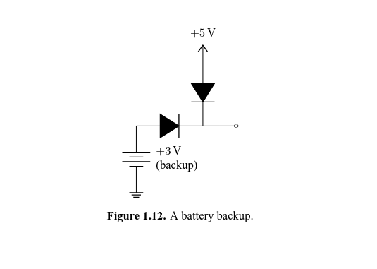
Continuous operation shouldn’t be a problem, but there are ways to reduce the power consumption of you want to.
Look for the duty cycle on the datasheet. The only relays I can think of with less than 100% duty cycle are automotive starter solenoids.
Thanks, that’s good to know! The datasheet doesn’t seem to include the word “duty” anywhere, so I think that must have been omitted. Ostensibly that means the maximum duty cycle is unlimited, but I don’t have enough experience here to say that with any confidence.
Unless otherwise specified at certain loads, relay duty cycles are always 100%.
Most relay duty cycles are in relation to switching currents, not the coil operation. There is always a slight resistance between dissimilar contacts, and carrying current across the contacts creates heat, so they have a max rated current for continuous use. They can often exceed this, but only for short periods before needing a duty cycle cooldown.
When the relay switches high near-max currents, especially in DC, it generates a large arc across the contacts. This makes them heat up. This limits the actuation frequency because too many arcs at max/overcurrent will overheat the contacts and could cause them to fuse together.
But the coil itself is designed such that it will never overheat on it’s own just from the trigger voltage. Granted it’ll waste a lot of power to resistive heating that is undesirable if your goal is power efficiency, but it will be perfectly OK.
I’m a little new to the terminology, so to clarify, the switching current refers to the amperage across the terminals other than the coil, right? I’m definitely within those limits; I don’t expect to transfer more than ~1/8 of the maximum amperage.
Is there a rule of thumb for the minimum current I should allow across the coil? The only specification I see on the datasheet for coil amperage is that it was tested to failure at 100mA. I don’t think power consumption is too big of a deal with this use case, but resistive heating sounds like it could shorten component life (and even if it’s only a secondary consideration here, I’d still prefer to minimize waste).
the switching current refers to the amperage across the terminals other than the coil
Yes. “Switching current” is the load current being controlled across the main contacts. I figured you were well within specs, I was just clarifying what typically limits relay duty cycle other than the coil.
Is there a rule of thumb for the minimum current I should allow across the coil?
Stick to the rated coil voltage in the datasheet or below and you’ll be fine. They set the coil resistance to be within the safe current zone per V=IR at rated control voltage.
Many relays can reliably switch well underneath their rated control voltage depending on their design- there’s a lot of safety factor built in. I’ve had some 12v automotive relays switch successfully at around 5v (by accident, lol). Experiment a bit and you may be able to cut down on waste power
Just be aware that control voltage (coil) and rated switching voltage (load) is often different, since many relays use low control voltages to switch high voltage loads. Don’t confuse the two!
Find a latching relay. I built something similar where I had a battery powered circuit that needed to be on for a long time. This is different than making a latching relay from a normal relay. A latching type relay uses a pulse. You send a short pulse down the line and it flops over. The datasheet will tell you the pulse width.