They are called soft termination, I’m not sure if that’s available for every component, it came to my attention on ceramic caps. It’s a dedicated feature you can filter components e.g. on Digikey.
- 2 Posts
- 14 Comments
Joined 1 year ago
Cake day: June 9th, 2023
You are not logged in. If you use a Fediverse account that is able to follow users, you can follow this user.
I’d say that’s a version of a soft termination capacitor. They are used when there’s risk the board is flexed or exposed to mechanical or thermal shocks to prevent cracks in the capacitor (causing it to fail short).
Not sure if that helps your research. We have an (very expensive “upper 4 digit region” they didn’t tell me exactly) DJI drone (an Matrice 30T if I remember correctly) at work that has the option of operating autonomously with a base-station where it also automatically lands and recharges. The catch is it’s like impossible to operate autonomous UAVs here because of airspace restrictions (that’s why we only have the “manual” version without that base-station thingy). I’m not directly involved in the department that operates the drone so I don’t have more in depth insights but maybe that already helps a little.
Fun fact, our military had to cancel a large and very expensive drone program because the drone (a little larger one tho) couldn’t get certified in European airspace (“Eurohawk” if you want to google that). So I’m not sure how easy it will be to hack something together depending where you are in the world and what restrictions say there.
I’m sure https://lemmy.world/c/pcmasterrace can help :)
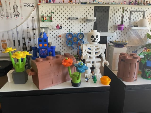
Wet sanding (with appropriate sandpaper) makes a huge difference, especially for smaller grid sizes.
But it’s probably easier to just get some individual pieces from Bricklink.

 3·1 year ago
It’s not really missing, there’s some life-insurance fraud going on.
 1·1 year ago
For example these things here:
 1·1 year ago
Mine is the smallest one of a series of these, it has two heating elements inside.
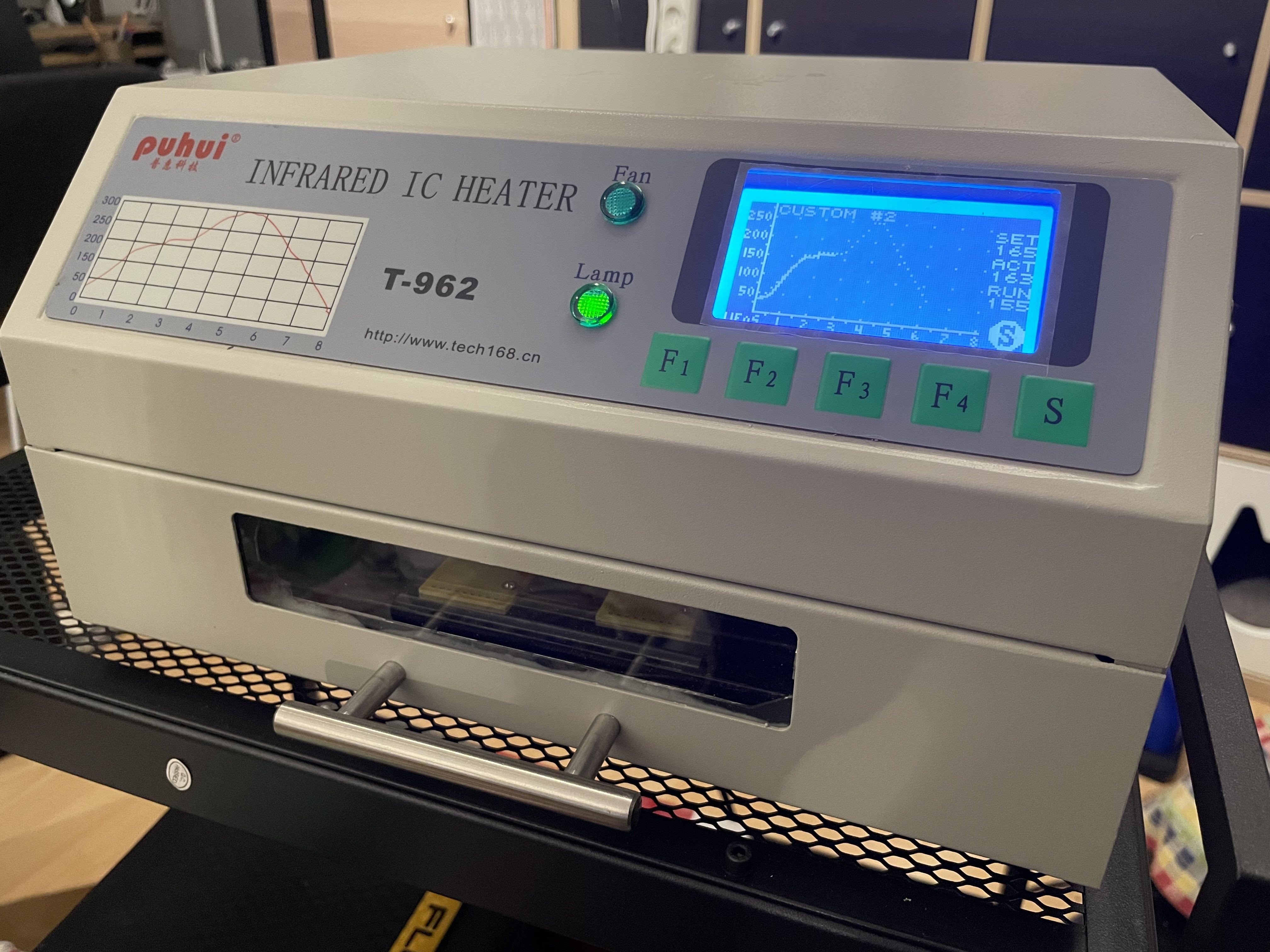
I don’t have it for that long but I didn’t have problems so far, I’m usually only making rather small PCBs tho. I did make some recommended modifications like replacing the paper insulation tape with a kapton tape, proper grounding and flashed another firmware.
I did only use a small hotplate and/or a hotair station, so it seems to be definitely a stepup here 😌.
I was kind of afraid of SMD things in general a long time but I discovered they are (up to a certain size, 0603 is still okay for hand assembly if you’re patient) comfortable to work with. Even QFN packages are okay if you have access to a hot-air station. I did actually order an BGA sensor out of curiosity along with other things, looked at it and was like “hahaha, thanks, I probably better don’t design that thing into my circuit” (I think it’s a 5-WLCSP package).
Yeah I have such a small, cheap Chinese one (T962) that I modified and flashed a nicer firmware on.
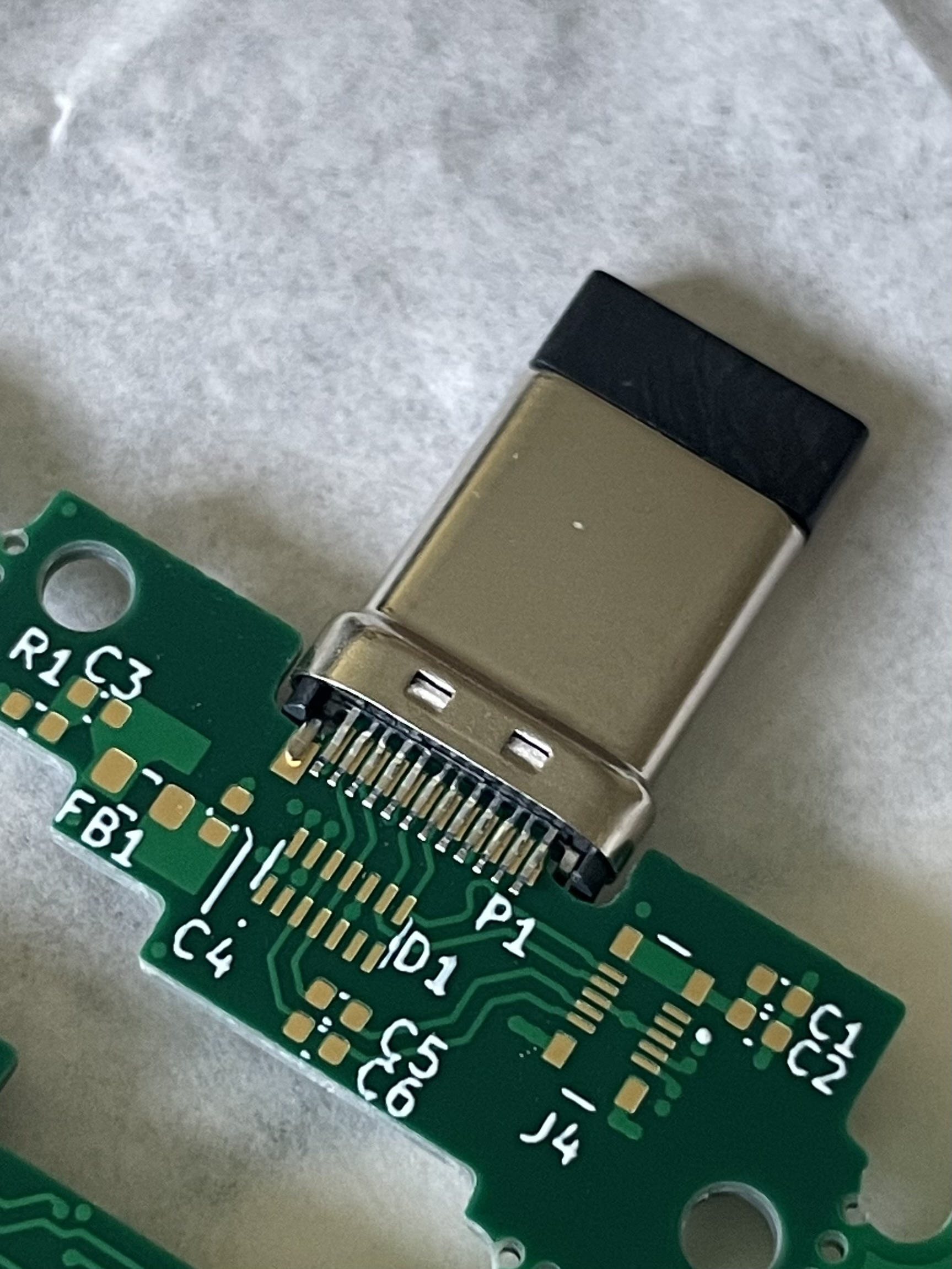
I basically populated the bottom side (with more components) first after applying solder past with a stencil, then reflowed the board. After cooling down I applied the solder paste to the upper side (with the LED) by using a small needle on a syringe (because using a stencil was too weird since the board wasn’t laying flat) but since the pads are relatively large and not that many that worked fine. Then I placed the components on that side and simply run the reflow cycle again.
I started with the bottom side because there are no heavy components. I expected heavy parts to just fall off on the second reflow cycle so I tried to avoid that.
At the end I manually assembled the USB connector using a regular soldering iron and tons of flux gel.
 1·1 year ago
Maybe you can use this to find more connectors that could match yours: https://connectorbook.com/identification.html?m=NT&n=lo_prof_1r_w2b_conn_1p2 It has a pretty handy identification tool (you can even browse by pictures). It usually suggests quite an amount of connectors but it can guide you in the right direction and you can look at the according datasheets to find out more. By the way the creator of this community made that homepage and a book related to it (or probably the other way round 😅).
It actually depends, on longer posts they somehow disturb the reading flow for me (because they are kind of distracting compared to plain text). For short comments on the other hand I like them and find them rather refreshing.
Thanks for starting a new home for the community ☺️.
Do we like emojis here or rather not? :D
Maybe this: https://www.microchip.com/en-us/product/PCI11400 Unfortunately to access the whole datasheet you might have to sign an NDA (and probably have a large company), also designing things with those kinds of interfaces isn’t trivial.
Alternatively maybe this: https://www.renesas.com/us/en/products/interface/usb-switches-hubs/upd720202-usb-30-host-controller It also seems to be locked by an NDA.